
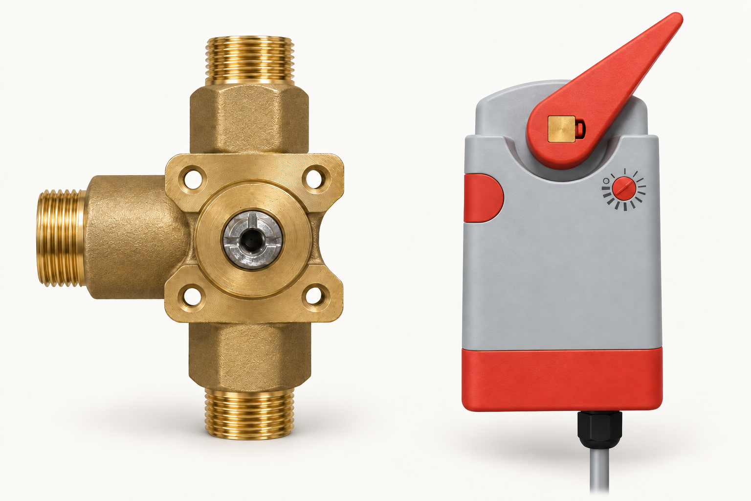
Start with the unnotched side down.
Turn the valve spindle so its three notches point up, left and right. The side with no notch points down, toward the source inlet. This is 0%: maximum recirculation.
Read it from the front.
Look straight at the exposed spindle. Keep the room loop above and the source supply and return below.
Keep this valve position while fitting the actuator. For the first setup below, the valve is on the right and the actuator turns clockwise as the command increases.
Watch the valve and spindle move.
Watch the valve turn and compare the view looking into each port.
Use the manual-release button.
Press and hold the button on the actuator’s left side to release the drive, then move the lever to the starting position. Release the button to restore motor operation.
Three wires to run. Feedback is optional.
With power isolated, connect the pictured actuator to Ceiling mixing or Floor mixing on the plant controller. This example uses its 24 V DC wiring.
| Actuator lead | Controller contact | What it does |
|---|---|---|
| Brown · BR | 24 V | Positive DC supply |
| Black · BK / COM | 0 V | DC and signal common |
| Yellow · Y / input | Vout 0–10 V | Command: board → actuator |
| White · W / FB | Vin 0–10 V · optional | Feedback: actuator → board |
| Blue · BL | Not connected in DC use | AC supply lead; insulate separately |
Insulate the unused blue lead separately. If feedback is not fitted, also insulate the white lead and leave Vin empty. Match the colours to the label on the fitted actuator.
One final check.
On the leader, open Test mixing valves. Check the fitted circuit at 0%: maximum recirculation, then 100%: maximum source flow. Allow the actuator to finish moving, then select Exit test to restore automatic control.
Entering the mixing test initially commands both mixing valves to 0%. Repeat the fitting sequence for the other circuit.