
Before you start
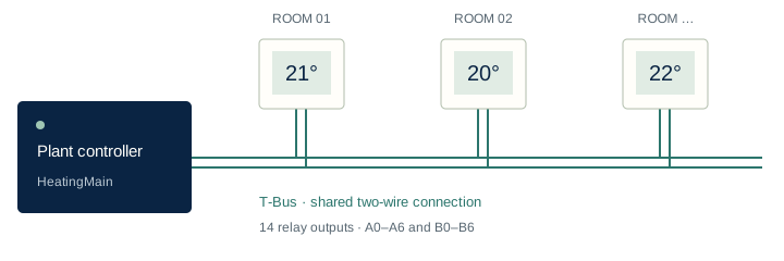
This guide covers system planning and the controls used to commission installed Ampernova hardware. The plant controller manages the actuators, circulation pumps and mixing valves; each wall thermostat supplies room temperature, humidity and demand over the T-Bus.
The plant controller connector map identifies the supplied board’s connectors, pin functions and zone labels. Relay load ratings, external relay-common wiring, cable limits and analogue signal ranges still need a matching electrical specification. Confirm those before making electrical connections. Installation and electrical checks should be carried out by a qualified installer with the supplies isolated.
Controller & thermostats
The plant controller, wall thermostats, specified supplies and matching firmware for the installed hardware.
Plant equipment
The designed heating/cooling source, actuators, mixing valves, circulation pumps and pipe/buffer temperature probes.
Installation records
Hydraulic plan, board wiring sheet, relay schedule and a room-by-room list of ceiling and floor circuits.
For optional integration
A compatible Matter controller and its required network, or the network configuration for the portal or local MQTT.
Plan the circuits
Record the physical relay that drives each room’s ceiling and floor actuator. Use the zone pin callouts for wiring and the same zone name for the thermostat selection. An address consists of a bank, A or B, and a channel, 0 to 6.
| Address | Purpose | On a thermostat? |
|---|---|---|
A0–A6 | Seven actuator relay outputs | Yes, for a connected circuit |
B0–B6 | Seven actuator relay outputs | Yes, for a connected circuit |
A7 | Ceiling circulation pump | No — reserved for the pump |
B7 | Floor circulation pump | No — reserved for the pump |
NC | Circuit not connected | Use for the unused ceiling or floor |
There are 14 actuator outputs and up to 14 thermostat identities. Separate ceiling and floor actuators in one room use two outputs. Seven rooms with two separate circuits each, for example, use all 14 outputs.
Plan one coordinating thermostat
A thermostat’s identity is the smaller non-zero of its two circuit addresses. The unit assigned A0 on either circuit becomes the leader. Its menu includes the system-wide Mode, Fabric and Dew settings. Plan exactly one leader and avoid assigning an output to more than one thermostat.
| Room | Ceiling | Floor | Role |
|---|---|---|---|
| Living room | A0 | B0 | Leader; both circuits |
| Bedroom | A1 | B1 | Follower; both circuits |
| Bathroom | NC | B2 | Follower; floor heating only |
The Ceiling and Floor menus identify the circuit’s purpose; the bank and channel identify its physical relay. Do not infer a circuit’s function from the bank letter alone.
Connect the system
Start with the whole-system schematic, then use the equipment wiring callouts for the 24 V supply, thermostat bus, probes and mixing valves. Follow the zone assignments for room actuators and the pump and neutral callout for the relay common.
- Check the installed plant. Confirm the hydraulic circuits, actuators, mixing valves, pumps and temperature probes match the design. Follow the equipment instructions for filling, venting and electrical checks.
- Connect and label the controller outputs. With supplies isolated, follow the board wiring sheet and relay schedule. The pump connector’s bottom contact takes the common neutral feed for all relays. Connect the two pump outputs by their numbered pin assignments in the pump callout. Mixing-valve return-voltage feedback is optional. For fitting, left/right pipe layouts and polarity checks, use the mixing valve and actuator installation guide.
- Connect the thermostats to the T-Bus. Connect either bus wire to either thermostat terminal; the thermostat connection works in both directions. Follow the specified cable, supply and termination requirements for your boards. The T-Bus uses a custom protocol; a generic Modbus controller is not a substitute for HeatingMain.
- Fit the room thermostats and plant probes. Use the hardware mounting instructions and planned sensor locations. Label each thermostat with its room and each actuator with its output.
- Inspect before applying power. Complete the hardware-specific electrical checks, then power the system according to its wiring sheet. Verify the thermostats refresh and respond to touch.
The display retains its last image without power. Confirm a fresh display update and touch response rather than relying on a visible temperature alone.
Assign the thermostats
Use the thermostat’s own screen. Tap the hamburger icon to open the menu at Info. Use Up and Down in the left navigation column to move between screens; the adjacent item icons show your position. Tap Home to return to the room temperature.
Choose the same bank and channel on the thermostat: board A0 is thermostat A0, and board B6 is thermostat B6.
- Open Ceiling. Select the bank and channel printed on the board for the room’s ceiling output. For example, select
Aand then3forA3. SelectNCif no ceiling circuit is connected. - Open Floor. Select the zone printed on the board for the room’s floor circuit, or
NCif it is not connected. - Check the displayed address after each change. A complete bank/channel selection writes immediately. A bank selected with no channel does not save a new address; NC takes effect immediately. If a channel is already selected, switching banks changes the complete address immediately.
- Confirm the leader. On the thermostat with A0 assigned, check that Mode, Fabric and Dew appear in the menu. The leader’s home-screen top band is inverted. Other thermostats have Info, Version, Ceiling and Floor.
- Record the room details. Open Version to read the firmware version, relay address pair and hardware UID. Record them with the room and actuator labels, then repeat for each thermostat.
The controller reports conflicting addresses; it does not choose replacement relay assignments. Check both circuit addresses on the affected thermostats and correct the duplicate to match the physical wiring.
Commission the plant
Set the operating mode on the leader
On the A0 thermostat, open Mode and choose Heat, Cool, Auto or Off to suit the installed plant and commissioning task. This is a system-wide choice: follower thermostats follow the plant’s season. Each room retains its own temperature targets.
Verify the readings and each circuit
- Check room and plant readings. Confirm plausible temperature and humidity in each room. Open Info to inspect the buffer tank and both mixing valves. Resolve missing or implausible probe readings before testing heating or cooling.
- Request heat in one room. In Heat mode, tap the temperature or the bottom-right setpoint to open the setpoint dial. Raise the target enough to create demand. Confirm the intended actuator responds and that another room’s output is not being driven.
- Allow the system time to respond. Thermostats communicate in a 60-second bus round. Each circuit’s pump starts only after one of its valves has been commanded open continuously for three minutes. Demand changes also have an anti-chatter hold, so repeated rapid setpoint changes are not a useful test.
- Check both circuits where fitted. The floor carries the primary heating demand; the ceiling joins at higher demand. Confirm that actuator labels, thermostat assignments and actual flow agree for each circuit.
- Check cooling where supported. With a cooling-capable plant, select Cool on the leader and lower a ceiling-equipped room’s target to create demand. Verify ceiling operation. The floor pump must remain off; floor-only rooms do not cool.
- Restore the intended settings. Return to the agreed operating mode and room targets. Check for active errors before moving to handover.
The leader’s Dew menu sets the safety margin; the documented default is 1.5 °C. The plant may raise the ceiling water target or veto a room’s cooling request when the dew limit is reached. A veto remains in effect for 10 minutes. Do not reduce the margin simply to force a cooling test through.
Use the thermostat’s bottom-left circuit indicators to inspect valve and pump state. Tapping them cycles between the normal view, relay addresses and the 48-hour open-percentage view.
Add the connected extras
Local operation does not require these steps. Complete the plant and room checks first. The wall thermostats communicate over the T-Bus; the plant controller provides the Matter bridge.
Matter smart-home setup
- Prepare the compatible Matter controller and the network it requires for the installed plant controller.
- On the A0 thermostat, select Fabric, then the MASTER tab. Tap START COMMISSIONING in the content area. Selecting the tab alone does not start pairing.
- Wait for the plant controller’s QR code and manual pairing code, then follow the smart-home app’s add-device flow. The request has a 70-second timeout; if it expires, use TAP TO RETRY.
- Check that the expected physical thermostats appear, and label their rooms. System mode remains controlled through the leader; other rooms follow the plant.
Owner portal
On the leader’s Fabric screen, select PORTAL, then tap GET PORTAL QR. When the QR arrives, scan it or open the displayed apnv.cc/p/… address and follow the portal flow. This online service needs the relevant network connectivity. Keep the portal access link with the owner’s records, rather than in a public installation photo.
Local Home Assistant integration
The controller also supports MQTT with Home Assistant discovery on the local network. This requires a reachable MQTT broker and controller network/broker configuration. Use the configuration for the installed firmware; the thermostat’s Fabric screen does not configure MQTT.
Troubleshooting on site
Record the room, both relay addresses, firmware version and hardware UID from Version, together with the displayed error. An error QR on the home screen links to the corresponding diagnostic address.
The screen is visible but does not respond
E-paper can show an old image with power removed. Verify supply and bus connections against the hardware wiring sheet and confirm a fresh refresh. If an update is in progress, let it finish before diagnosing the touch controls.
The thermostat shows NO CON or a Nocom QR
The thermostat has lost communication with the plant controller. Check controller power, the T-Bus connection and the thermostat’s circuit addresses. Confirm compatible firmware on both ends and allow a full 60-second communication round after correcting the cause.
Mode, Fabric or Dew is missing
These menus are only on the A0 leader. Check the Ceiling and Floor assignments: the unit’s identity is the smaller non-zero address. Plan one thermostat with A0 assigned to its actual circuit, then verify the expanded menu on that device.
A duplicate address is reported
Error bit 7 indicates an address conflict (displayed as ERROR:128 when it is the only error). Check both ceiling and floor addresses across the affected units, including shared secondary outputs. Correct the assignments manually. Conflict indications can take 3–10 minutes to clear depending on the detection path; record persistent errors rather than assuming a new address is enough.
The pump has not started
First confirm that the correct circuit has an open-valve command and real demand. Its pump waits until a valve has been commanded open continuously for three minutes. The floor pump is disabled during cooling. If the command is present after the delay but the pump does not run, inspect the output and plant wiring using the hardware procedure.
Cooling pauses or a condensation marker appears
The plant can raise the ceiling water target or pause cooling at the dew limit. Check room humidity, ceiling pipe temperature and the configured safety margin; a cooling veto lasts 10 minutes. Floor-only rooms cannot cool. Do not bypass the protection to restore demand.
The wrong room heats, or a circuit stays off
Compare the physical actuator wiring with both relay selections on each thermostat. Verify that NC is only used for an absent circuit and no output is claimed by another unit. In a combined room, a modest heat request may run only the floor; the ceiling is added at higher demand.
The pairing or portal QR does not arrive
Use the leader thermostat. Open Fabric, choose MASTER or PORTAL, then press the separate action button. Check bus communication and the controller’s required network connection. Wait for the 70-second request timer, then use TAP TO RETRY if needed.
The handover checklist
Work through these checks with the homeowner and retain the completed printout with the room schedule. Checks are for this page session only; they are not saved as an installation record.