
Supported systems
The master HM always drives the Stiebel WPM source-control outputs. There is nothing to select on the thermostats, and a slave HM never drives the source.
If no heat pump is wired to the two outputs, they have no effect. Room control, mixing valves and shared pumps work the same either way.
Stiebel WPM integration is implemented and simulation-tested. Electrical validation on the connected heat pump is still pending. Other systems are not yet supported.
Source water temperature
The HM requests 45 °C for heating and 17 °C for cooling when rooms need it, including rooms on slave HMs.
- Heating requests 45 °C whenever a ceiling or floor circuit needs heat.
- Cooling requests 17 °C. Mixing valves manage dew-point protection, including humidity from slave rooms. Floor demand never requests cooling.
- Once on, the heat pump stays on until no room has called for 24 hours, or until no room has needed the current season for 30 minutes. Then both source outputs go to 0 V.
- From off, a call starts the heat pump once it has been off for 6 hours and the call has lasted 3 hours without a break. When the rooms’ average demand is above 50 %, the 3 hours are skipped. The portal shows when it will start.
- Pumps retain their three-minute actuator-opening delay.
- Humidity changes the mixing-circuit target, not the source temperature. Room condensation protection can still stop cooling demand.
No temperature entry is needed, and the requests are commands, not heat-pump feedback.
Stiebel WPM
Two 0–10 V outputs request the operating mode and water temperature. The WPM keeps control of compressor timing and its internal protections.
Physical wiring
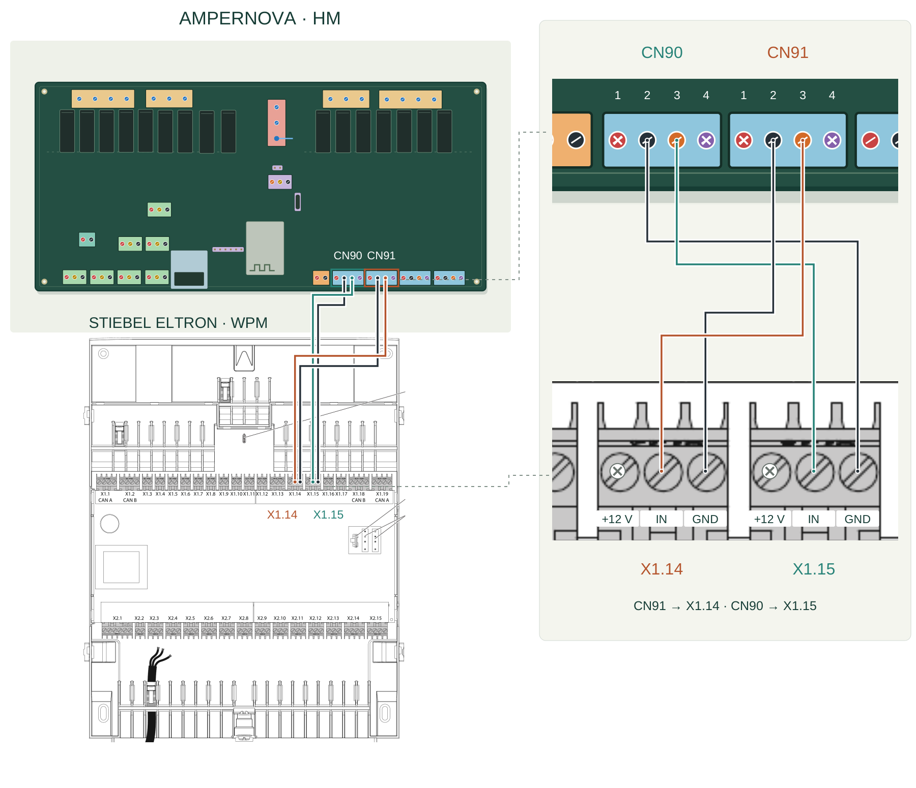
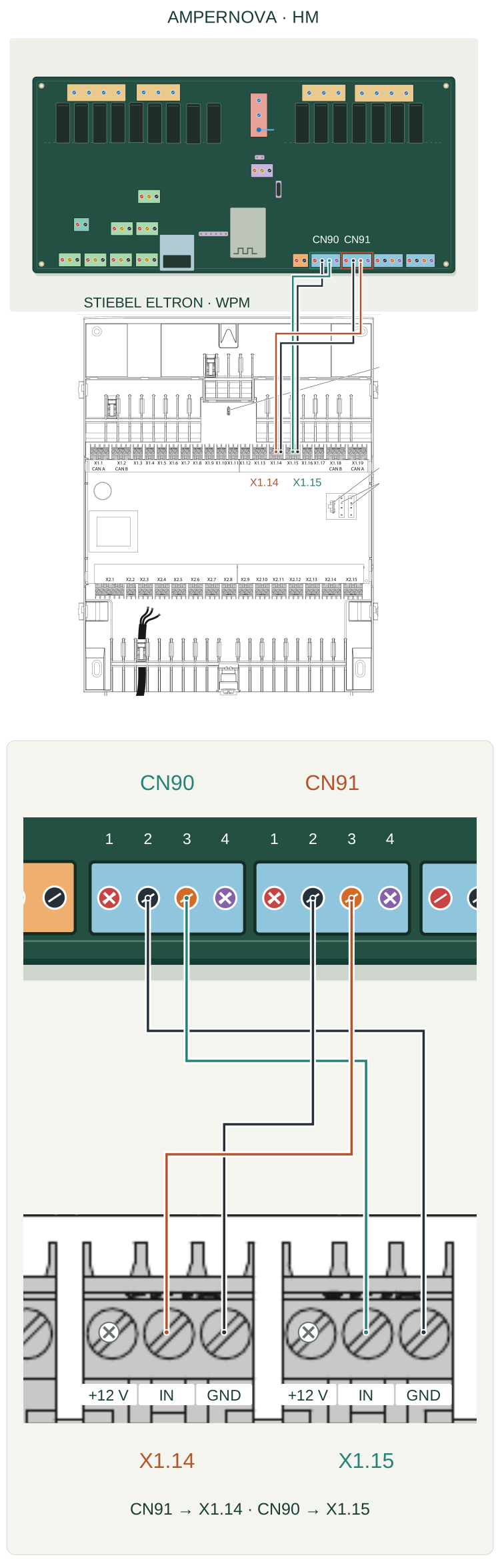
Open the complete wiring drawing → · Open the stacked mobile drawing →
WPM photographs
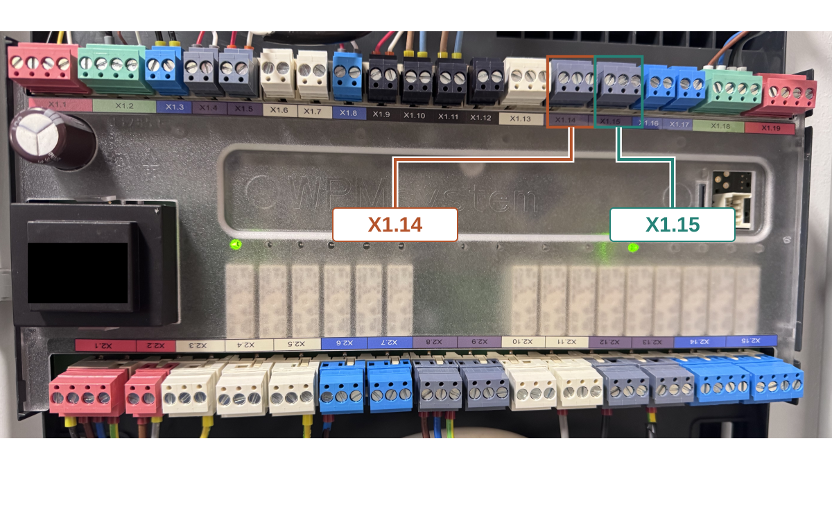
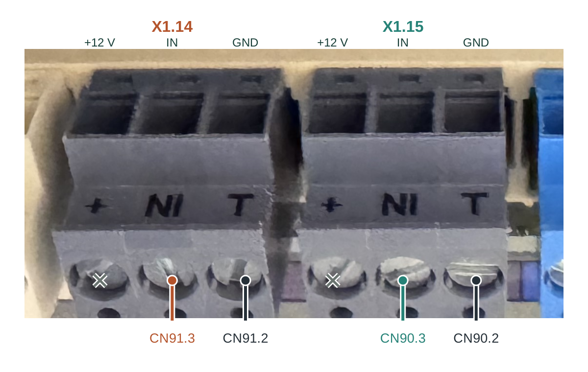
Viewed from the front as shown, each WPM plug reads left to right: +12 V, IN, GND. Leave the left contact (+12 V) empty. Connect the HM signal to the middle contact (IN) and the HM analogue return to the right contact (GND). Orange is X1.14 mode; teal is X1.15 temperature. Match the printed markings on your controller.
| WPM input | Left: +12 V | Middle: IN | Right: GND |
|---|---|---|---|
X1.14 | Leave empty | CN91.3 | CN91.2 |
X1.15 | Leave empty | CN90.3 | CN90.2 |
| HM output | WPM input | Function |
|---|---|---|
CN91.3 / GPIO12 | X1.14 IN | Mode: 0 V off, 3 V heating, 8 V cooling |
CN90.3 / GPIO13 | X1.15 IN | HM water target |
CN90.2 / CN91.2 / 24VGND | GND | Analogue signal return |
Use the conditioned Vout terminals, not raw GPIOs. Leave the WPM’s + supply terminal and the HM’s +24 V terminal disconnected from these signal inputs.
Leave HM pin 4 (feedback) disconnected too. Use pin 2 (24VGND) for each analogue return; CN89 signal GND is a different net.
Locate CN90 and CN91 on the PCB wiring guide →
WPM menu setup
The WPM only follows X1.14 and X1.15 once they are switched on in its own menu. The settings are in the commissioning menu, which asks for a code. The factory code is 1000.
- Open
COMMISSIONING → I/O CONFIGURATION → INPUT X1.14and selectEXTERNAL HEATING/COOLING. WithOFF, the WPM ignores the HM’s mode signal. If your WPM shows separateHEATINGandCOOLINGswitches underINPUT X1.14, set both toON. - In the same menu, open
INPUT X1.15 → HEATINGand setPRESET TEMPERATURE 1 Vto 10 °C andPRESET TEMPERATURE 10 Vto 60 °C. - Open
INPUT X1.15 → COOLINGand setPRESET TEMPERATURE 1 Vto 9 °C andPRESET TEMPERATURE 10 Vto 20 °C. - For cooling, also prepare the WPM itself: switch on
SETTINGS → COOLINGand setSUMMER MODEtoON, which the newer WPM manual requires for external summer control. Check the manual’s other conditions for cooling operation for your heat pump. Fixed-value operation must be off, because the WPM does not cool with it on.
The HM computes its water request from exactly these endpoints. With other values, the WPM reads a different temperature from the same voltage.
| Voltage on X1.14 | WPM | HM sends |
|---|---|---|
| 0–1 V | Off | 0 V: nothing requested |
| 1–5 V | Heating | 3 V |
| 5–6 V | Off | Never used |
| 6–10 V | Cooling | 8 V |
The HM sends values in the middle of each band, never on a boundary. X1.15 then sets the water temperature within the selected mode: 45 °C heating is 7.3 V, 17 °C cooling is about 7.5 V.
With buffer operation on (SETTINGS → HEATING → STANDARD SETTING → BUFFER OPERATION), the request sets the buffer temperature. Otherwise it sets heating circuit 1.
To give control back to the WPM, set INPUT X1.14 to OFF. A 0 V output does not do that: it only means the HM requests nothing.
Commissioning
- Before connecting the WPM, confirm the controller’s external-input functions and measure both outputs against their analogue return.
- Set up the WPM menu as above. Check the mode and target displayed by the WPM.
- Test demand from each HM, heating and cooling, idle shutdown and the pump delay. An output command does not confirm compressor operation.